
ECE 2090 Logic and Computing Devices Laboratory (23 Fall, 23 Spring, 22 Fall)
Undergraduate lab, Clemson University, Holcombe Department of Electrical and Computer Engineering, 2023
Introduction to designing, building, simulating, and testing digital logic circuits. Topics include SSI and MSI ICs; general combinational circuits; adders, decoders, and multiplexors; general sequential circuits; shift registers, counters, and memory.
This webpage displays a curated collection of elements utilized during the instruction of this lab.
Lab course background
This lab is accompanied by ECE 2010 Logic and Computing Devices at Clemson University. Students are expected to perform circuit board building using 74-series chips and gate-level logic simulation using Logisim Evolution, with lab-related simulation details listed in Logisim Evolution tutorial.
This lab serves as a gateway, offering more than just a surface-level understanding. Beyond the apparent simplicity lies a foundation for intricate knowledge, laying the groundwork for the intricate tapestry of electrical and computing principles. The concepts introduced here not only provide immediate practical application but also serve as stepping stones for advanced exploration in the realm of digital design. The extra materials for students’ interests aim not only to spark curiosity but also to ignite a passion for delving deeper into the intricate world of logic and computing.
In this lab course, the final evaluation is a final/capstone project rather than an exam. Students are tasked with designing a larger-scale digital project to meet the course requirements. While lab final project prompts offer possible topics, students are free to choose their own based on their interests.
Logisim Evolution tutorial
Download address
Logisim Evolution is conveniently available from the website https://github.com/logisim-evolution/logisim-evolution
Download the package as listed for different operating systems: Windows user, please use logisim-evolution-
Note that there may be an issue with Logisim evolution, which causes some downloaded files to have a .circ extension. You can fix it using the method here.
https://github.com/logisim-evolution/logisim-evolution/issues/1471#issuecomment-1332917265
“Removing the registry key HKEY_CLASSES_ROOT\MIME\Database\Content Type\application/octet-stream\Extension instantly resolves the issue.”
Basic usage tutorial
The draft of the basic usage is avalible below:
Extra materials for students' interests
There are 10 lab sessions in this lab course. Below are the collected extra materials, apart from the lab manual, related to the corresponding lab content: theory, simulation, and circuit board building. The original webpage was designed for a Canvas page. Click the image to be redirected to the corresponding YouTube URL.
Lab 05, 06, 07 Binary arithmetic, MSI circuit, Multiplier
Lab 08 Mux and serial communication
Lab 01 Course Description
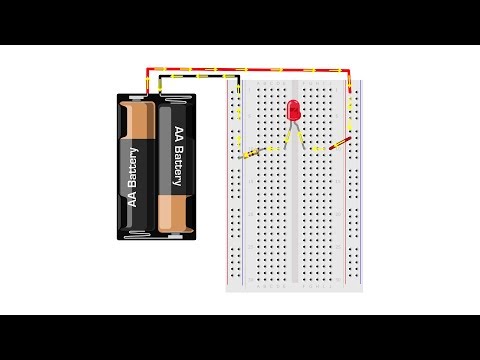
What’s inside the breadboard?
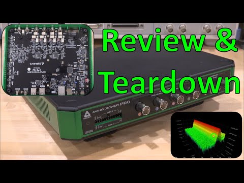
What’s inside Analog Discovery 2 from the signal path?
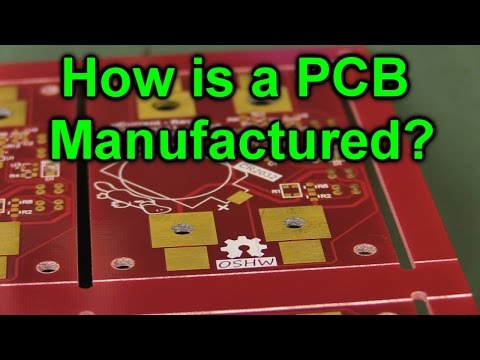
PCB manufacturation.
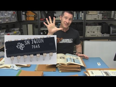
First 74 series chip.
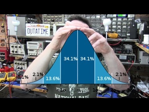
Resistor value distribution.
Why was the resistor burned?

How to use the IC pin straightener?

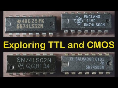
Difference between TTL & CMOS, 74LS/74HC.
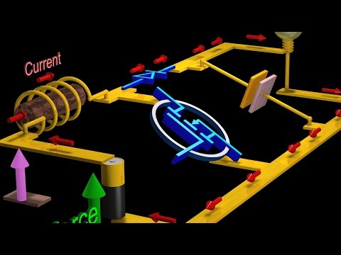
Switch-mode power supply, Boost Converters and Buck Converters: Power Electronics
Blowing Up LEDs for Science

Lab 02 Logic Gates
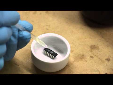
Decapping ICs.
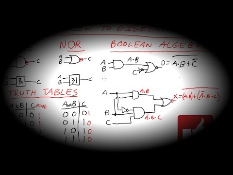
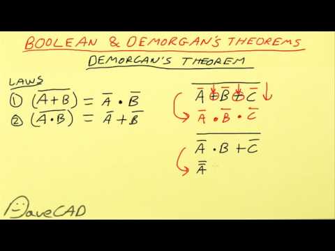
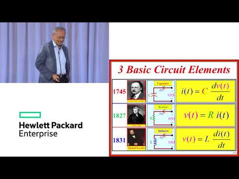
Introduction to digital logic.
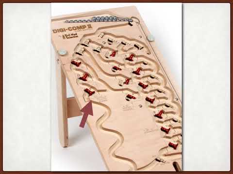
Digi Comp II.
Logic gates from a transistor

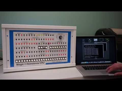
CPU built from TTL logic
MEGAprocessor
https://www.megaprocessor.com/index.html
Another CPU built from TTL logic
https://www.ttlcpu.com//articles/4-bit-ttl-scratchbuilt-computer
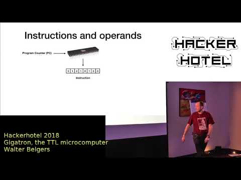
Gigatron TTL computer
A computer built from NOR gates: inside the Apollo Guidance Computer
https://www.righto.com/2019/09/a-computer-built-from-nor-gates-inside.html
Lab 03 Encoding/Decoding
Nixie Tube display

RGB LED Matrix display

Bad apple on the LCD screen
Bad apple on the oscilloscope
UTF-8/Unicode for general encoding
https://en.wikipedia.org/wiki/UTF-8

Lab 04 Combinational Circuit
Quine–McCluskey algorithm
https://en.wikipedia.org/wiki/Quine%E2%80%93McCluskey_algorithm
ABC: System for Sequential Logic Synthesis and Formal Verification
https://github.com/berkeley-abc/abc
Error correction code
https://en.wikipedia.org/wiki/Error_correction_code
Hamming code
Hamming code inventor’s famous talk: You and your research.
A brief introduction to LDPC code

LDPC code’s inventor Prof Robert Gallager talks about his advisor Shannon, the father of information theory
Lab 05, 06, 07 Binary arithmetic, MSI circuit, Multiplier
Binary arithmetic extension
- Floating point https://en.wikipedia.org/wiki/Floating-point_arithmetic
- unum (posit) https://en.wikipedia.org/wiki/Unum_(number_format)
Various adders(Brent–Kung adder, Kogge–Stone adder)
- Brent–Kung adder https://en.wikipedia.org/wiki/Brent%E2%80%93Kung_adder
- Kogge–Stone adder https://en.wikipedia.org/wiki/Kogge%E2%80%93Stone_adder
- Sklansky adder
- Han-Carlson
- Ladner-Fischer
- Knowles [2,1,1,1]
- Adder circuit generator https://github.com/IamFlea/AdderCircuitGenerator/blob/master/README.md
Various multiplier trees(Wallace tree, Dadda tree)
- Wallace tree https://en.wikipedia.org/wiki/Wallace_tree
- Dadda tree https://en.wikipedia.org/wiki/Dadda_multiplier
- Overturned tree https://ieeexplore.ieee.org/document/156536
CORDIC algorithm for computing sin/cos/square function
CORDIC algorithm https://en.wikipedia.org/wiki/CORDIC
How does a computer calculate?
Approximate computing
https://ieeexplore.ieee.org/stamp/stamp.jsp?arnumber=9165786 https://ieeexplore.ieee.org/stamp/stamp.jsp?arnumber=9170586
HDL tutorials
https://inst.eecs.berkeley.edu/~cs61c/resources/verilog.pdf
https://inst.eecs.berkeley.edu/~eecs151/fa23/
https://en.wikipedia.org/wiki/Verilog
https://en.wikipedia.org/wiki/VHDL
Chisel

High-level synthesis (HLS)
FPGA introduction

Karatsuba algorithm

Lab 08 Mux and serial communication
What is the difference between serial and parallel communication, and why do we need serial communication

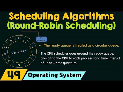
Round-robin scheduling from the Operating system
The difference between FDMA, TDMA, and CDMA in the communication system.
https://www.geeksforgeeks.org/difference-between-fdma-tdma-and-cdma/
Hedy Lamarr: Inventor of CDMA
https://en.wikipedia.org/wiki/Hedy_Lamarr 
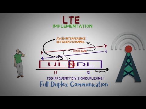
TDD and FDD in 4G LTE
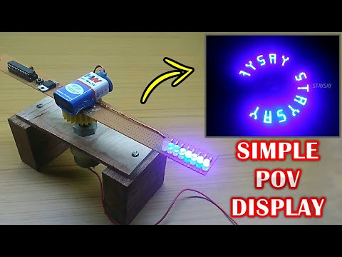
Screen Refresh Rate Experiment

Persistence of vision
https://en.wikipedia.org/wiki/Persistence_of_vision
How does a Universal Serial Bus(USB) work
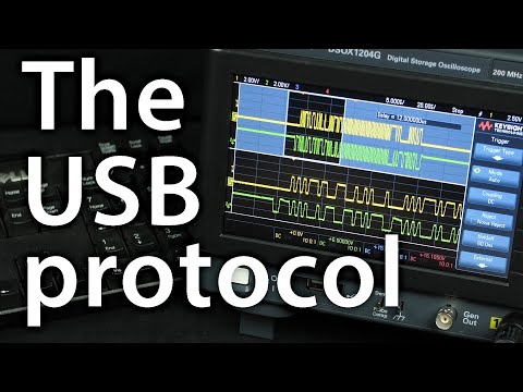
USB 101
Lab 09 Memory, Cache
3.5 inch floppy disk(the A disk)
5.25 inch Floppy disk(the B disk)

World’s Most Expensive Hard Drive Teardown

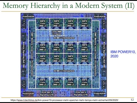
More detailed lecture on memory hierarchy
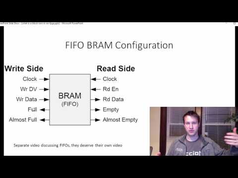
Block RAM/ROM in FPGA.
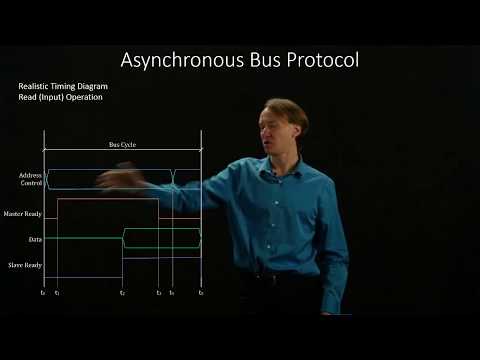
BUS control/protocol
Memresistor
Advantages of Near Flash Computing with Arvind
https://cap.csail.mit.edu/podcasts/advantages-near-flash-computing-arvind
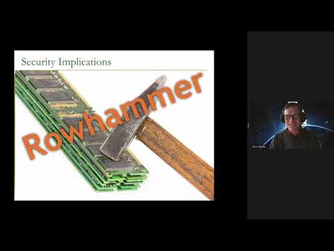
Rowhammer attack
Universal Memory Interface
https://github.com/zeroasiccorp/umi
Lab 10 Sequential design
David Patterson: Computer Architecture and Data Storage
View from the Top: Professor David Patterson
New Golden Age for Computer Architecture - John Hennessy
Static timing analysis
Computer History Museum
https://computerhistory.org/
1401 N Shoreline Blvd, Mountain View, CA 94043
Intel Museum
https://www.intel.com/content/www/us/en/company-overview/intel-museum.html
2200 Mission College Blvd, Santa Clara, CA 95054
Lab final project possible topics
This list was last updated by the end of Fall 2023 and will no longer be updated on this site. Feel free to use it if you need it.
Final project objective
This open-ended project involves the design, simulation, and analysis of a digital circuit related to a concept of the students’ choice. Students are tasked with thoroughly exploring all available components within the simulation software. Additionally, students are encouraged to consider integrating this project into their future endeavors across various courses.
Elements allowed and forbidden for simulation-only designs
Logic function exploration (extension of Lab 02 to Lab 04)
Various board games:
Topics:
- 2D version X and O.
- 3D version X and O.
- Chess.
- Rock, Paper, Scissors, Lizard, Spock.
- Sudoku game.
- Connect 4 games.
- Connect 4 games, geographic version, inspired by this video: https://www.youtube.com/watch?v=oZSUxdzgA08
- Gomoku game.
- Monopoly game.
Details:
- You need to design the basic game design for two players using combinational logic. Some games may involve underlying physical rules you need to follow. Please consider how to handle it.
- You can enumerate/compute all possible winning/losing/tie games for the players. You are recommended to design this part by using the combinational analysis.
- Design a simple strategy allowing a human-machine game interaction. It might be as simple as placing the O on the left of X, or you may refer to algorithms to simplify it into a more complex decision logic.
- The player needs to be prohibited from moving/changing another player’s moves. You also need to consider if the win/lose/tie happens, the player is no longer allowed to play unless the game is reset.
- User-friendly display to identify win/lose/tie situations.
- Store and update the player’s gaming record, win/tie/loss, after every game. You can probably consider using an integrated counter to tick the clock once such a case happens.
- The size of the “board” is highly recommended to be limited to 10 x 10 rather than a full/large scale, and the player number is limited to 2.
Meaningful LED display
Topics:
- Led display for public transportation.
Details:
- Store the letter for the LED display in memory or using combination logic (not recommended). Only including A~Z & 0~9 is fine, while you may consider other graphic displays (airplane signs) that may incur more overhead.
- Allow multiple patterns/colors for display:
- CATbus’s screen may display the pattern with rotation of RED-CLEMSON/RED-CENTRAL/GO TIGERS/BEAT XXX(change based on a specific football game)/Merry Christmas/Have a Nice Day.
- Long string display within the limited LED space: Suppose the screen can only display 5 characters to allow the user to see the entire word of CLEMSON. You need to display 【CLEMS】【LEMSO】,【EMSON】 cyclically. The shift register may realize this function.
Binary computation for different purposes (extension of Lab 05 to Lab 07)
General-purpose binary computing
Topics:
- Calculator
- Fast adder realization.
- Multiplier tree realization.
- Modular computation.
- Sequence generator
Details:
- Calculator
- 8-bit Addition/Subtraction/Multiplication. Please do this part by extending your design from labs 5, 6, or 7, or by using available 74-series chips in Logisim Evolution.
- Try out 8-bit Division.
- Fixed-point decimal operation.
- Show current computation type using LED matrix.
- Store prior computation results.
- Allow CE/C to function as the real calculator does.
- Fast adder and multiplication tree realization:
- Multiple fast adders and multiplier trees are introduced in the lab slide, which are listed as extra materials for students’ interest here. Please try to search for related references and design them.
- Try to examine the difference between different fast adders and multiplier trees.
Modular computation
- Modular computation is widely used for cryptographic operations, where the computations are typically done over a prime, like 17 or 19.
- You need to design modular addition, modular subtraction, and modular multiplication. You may refer to the following wiki pages for more details on the algorithms. https://en.wikipedia.org/wiki/Modular_arithmetic https://en.wikipedia.org/wiki/Barrett_reduction https://en.wikipedia.org/wiki/Montgomery_modular_multiplication
Sequence generator
- Generate the sequence by computation following the rule of generation. A typical example of a Fibonacci array.
- Show the sequence and sequence types using the display.
Sport scoreboard
Topics:
- American football scoreboard
- Basketball scoreboard.
- Tennis scoreboard.
Details:
- High-performance player/Team player statistics.
- Consider a timeout countdown, resetting the clock. One example could be the clock countdown in a basketball game. When the remaining second is less than ten, it will display one-tenth of a second.
- Resetting the scoreboard.
- English letter display for personal fouls.
- Simple time-multiplexed display for concurrent games.
- Other necessary display features.
Quiz buzzer
Topics:
- Quiz buzzer.
Details:
- Suppose there are multiple players/teams. You are expected to find the player who first presses the button and tries to answer the quiz.
- It is an add-on to the timer and clock. You need to design additional registers to sample the simulated push signal by using pins.
- It would be great to record whoever comes to the second and third, etc.
- It can also include a scoreboard as a subset to record team scores if they answer the question correctly or not.
Daily transaction
Topics
- Parking meter.
- Vending machine.
- Pill separator.
Details:
- For parking meter/vending machine:
- Accept quarter/half-dollar/$1, $2, $5 bills. You can consider pennies, dimes, and nickels.
- Counting the remaining available spots using sensors (use switch here to simulate).
- For pill separator: ** Countdown timer to decide which types of pills should be consumed. The time intervals can be reconfigured. ** Allow purchasing/consuming multiple types of parking time/merchandise/types of pills.
- Give change if needed using comparison logic. A good 74-series chip is 7485 in Logisim Evolution. Return bills if needed.
- Warning sign if low in stock/parking time is about to expire.
- Allow the user to load a custom amount of goods/pills if they are out of stock, and change the stock after loading.
- This design is supposed to be a sequential design. Every time (let’s say every second) you insert a bill/coin, the machine must record it and use the recorded amount to return change and goods.
Integrated counter application (extension of Lab 08, 10)
Topics:
- Traffic light (counter-based/memory-based).
- Using counters to replicate the iPhone clock.
- Fitness watch design.
- Washing machine simulation.
- Oven simulation.
- Microwave simulation.
- Refrigerator simulation.
Details:
Traffic light:
- Use an integrated counter or memory to design the traffic light.
- Left turn/pedestrian signal/sensor-based signal.
- Configurability of the different traffic phase-switching patterns (peak hour/night hour).
- Countdown clock for red & green light.
- Low traffic blinking light (blinking red/blinking yellow)
- Consider a train going through a Level crossing https://en.wikipedia.org/wiki/Level_crossing
- 4-arrow left turn signal.
- Consider green wave design for multiple intersections https://en.wikipedia.org/wiki/Green_wave.
- All sensor/external triggers can be abstracted as input pins.
Clock-based design for iPhone clock/Fitness clock/Home Appliances
- Basic clock feature with hour/min/sec with the decimal display.
- Basic timer for counting down with set/reset/display.
- Basic meter for counting up with set/reset/display.
- Record lap-wise time.
- The alarm clock design allows snoozing.
- Include possible simple control signals to the motor.
- You may consider displaying the time from 00:00 to 23:59 rather than 12:00 am to 11:59 pm.
Memory applications (extension of Lab 09)
Topics:
- Digital circuit functionality checker.
- Memory tester.
Details:
Digital circuit functionality checker for multiple 74-series
- You need to record the possible input/output pairs for the 74-series chips, like the physical ones in the lab.
- The physical tester in the lab room includes sequential 74-series chips, which could be challenging. You may consider how to extend it.
- The tester may need to automatically detect if the chip is 14 pins, 16 pins, or more.
- Connect the IC tester with the 74-series chip, and the tester enumerates all possible input vectors(multiple input pins) stored in the memory.
- You need to design a custom malfunctioning 74-series chip to verify its capability to indicate malfunctioning chips.
- Warning sign if the DUT has different functions and displays the malfunctioning input/output.
- Give hints for possible fixing methods with the proper display.
Memory tester
- This is similar to the memory/cache lab. However, here you need to use RAM via input/output pins rather than ROM.
- Create a RAM with read and write capability.
- Write in the custom meaningful data with bit-width 8 in two ways:
- Initialize the value stored in the RAM (all 0 is the special case), you need to find your own possible meaningful initial values.
- User custom data input (possibly with input/output pins or other good interface).
- Read the data from the RAM and properly store and display it.
- Users determine whether the current state is a read process or a write process. You can design your own read/write process patterns. Use an LED indicator for interaction.
- A practical example is:
- You store data “Hello World” in your memory by external output, NOT by initializing the stored value by hand as was done in Lab 9.
- Once the write process finishes, you read the memory, and possibly show the “Hello world” in the way you want to display.
- Introduce an error during multiple read/write iterations, and the stored data may become “Hello World”, and your display can show such a difference.
- Once you find there is an error, you can again write back the “Hello World” to the RAM.
Processor design (extension of Lab 08)
Topics:
- Simple ALU/processor design.
- Watchdog simulation.
Details:
Simple ALU/processor design
A typical instruction-based processor involves 5 stages: IF = Instruction Fetch, ID = Instruction Decode, EX = Execute, MEM = Memory access, WB = Register write back, refer to https://en.wikipedia.org/wiki/Instruction_pipelining
Here, having ID, EX, and WB stages using the gate-level design is doable. Having the EX stage is a plus. This design requires a clock signal.
- In the ID stage, you retrieve the instruction code from the register (D flip-flop)
- In the EX stage, you perform the instruction (arithmetic/logic operations). You have already done something similar in the MSI circuit lab; here, you need to extend it to a larger context.
- In the WB stage, you extract the computation result from the ALU, and display/store it in the way you want.
| clk 0 (ID stage) | clk 1~ -1 (EX stage) | clk -1 (WB stage) |
Extract the data from the data register. Extract the instruction code from the instruction register. Both instruction & data registers are connected with input pins. | Perform the computation within the ALU. It is possible that the instruction may take multiple clock cycles. Here, at most 3 clock cycles are needed for computations. | Extract the computation result from the ALU. Use the proper way to display (LED/7-seg) |
- Using MUX to instruct the processor for different operations for given operands.
- Possible operation include basic logic operation(AND/OR/XOR/XNOR etc) & basic arithmetic operation(ADD/SUB/Multiplication/Mod operation/Exponential operation)
- You can also make the design interactive by highlighting the current operation stage the ALU is working at.
- Try to minimize the total number of gates/ICs (make some of the gates/ICs multi-functional)
- Please refer to this link https://github.com/grself/CIS221_Lab_Manual/tree/master for alternative discussion.
Details: Real-life system design (extension of all labs)
Topics:
- Digital lock.
- Elevator simulation.
Details:
Digital lock
- Set and store the correct password with 4~10 digits using the input buttons
- Enter the correct password to unlock using the same input buttons.
- Cool down the period if the user has entered multiple incorrect passwords.
Elevator simulation
- Design the elevator for at least five floors.
- Users can push the up/down button to access the elevator.
- Consider possible override by firefighter/elevator operator.
- Please refer to this document for a more detailed description here in this file.
Other related online resources
- You can also refer to the playlist here for more details: https://www.youtube.com/playlist?list=PLvjlcTfwDj4spSN4g3S8IHbqY4Qkb5LxP
- The video is based on the lab manual available in this GitHub link https://github.com/grself/CIS221_Lab_Manual/tree/master